Vitri GPS SMS Security Tracking System
This project consists of a combination of the SIM900 3G modules, GPS and inertial motion sensor (IMU) together with the development card STM32F407 Discovery, in order to create a security system that will allow the user to receive alerts of possible anomalies in motorcycle (if it is down), as well as inform another user about the event of a crash or fall on the motorcycle in order to quickly locate the accident
Design
Idea
The focus of the idea is to find a way to help motorcyclists when they suffer an accident, since they are the vulnerable when they are on the road. This idea comes after seeing the number of accidents in the metropolitan area of Guadalajara.
Data
A consolidated report of the National Observatory of Road Safety (ONSV) recorded that, of the 7,158 deaths occurred in 2016 due to traffic accidents, 3,759 (52 percent) were motorcyclists: it indicates that every day 10 died on average
Objective
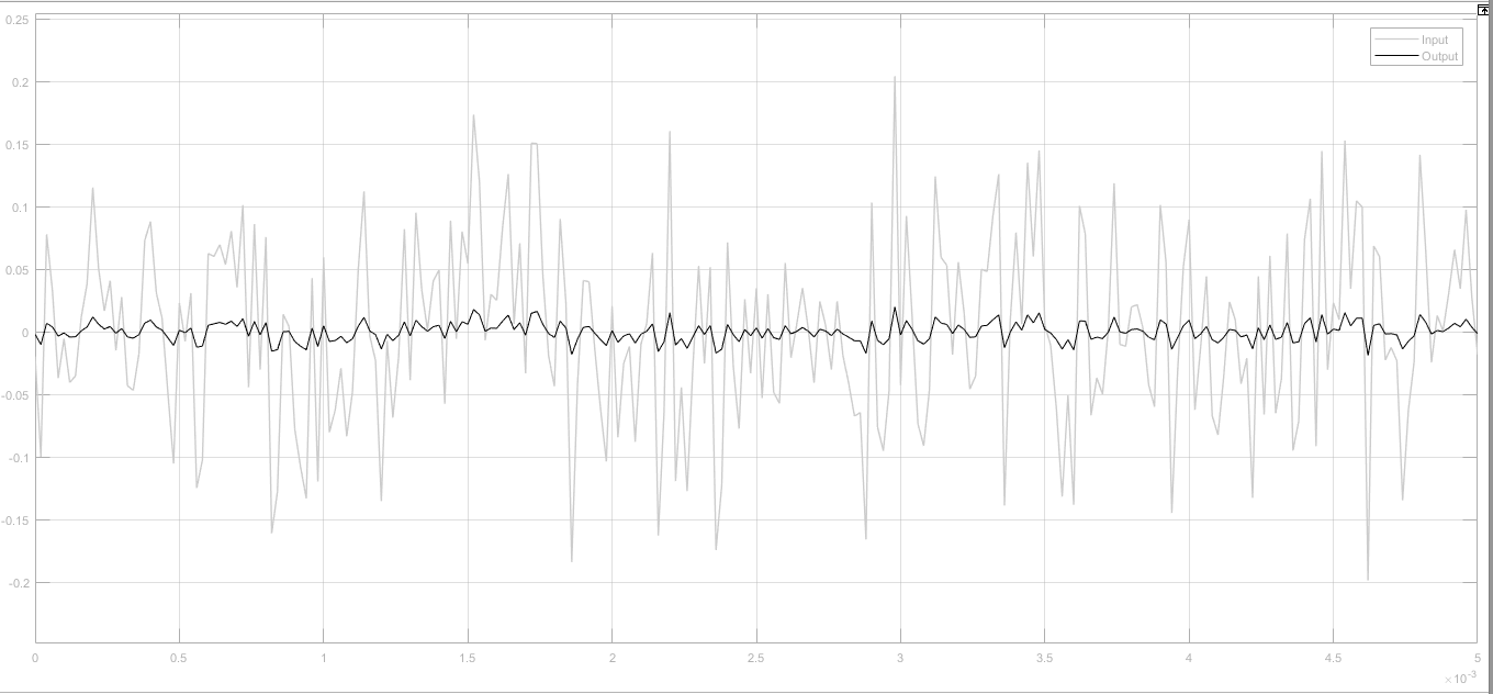
Create a product that can send SMS messages warning that a mishap occurred and the location of it to help the person who was on the motorcycle, to have a drastic change in G forces, calculated thanks to an IMU.
Hardware
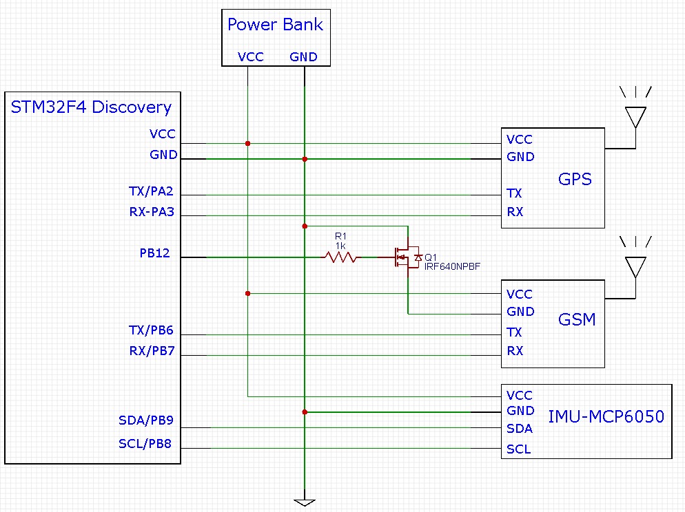
Schematic
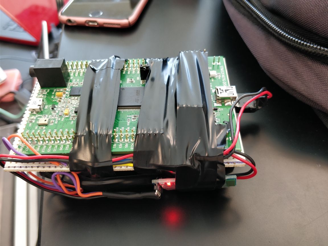
The following diagram shows all the modules connected to the development board.
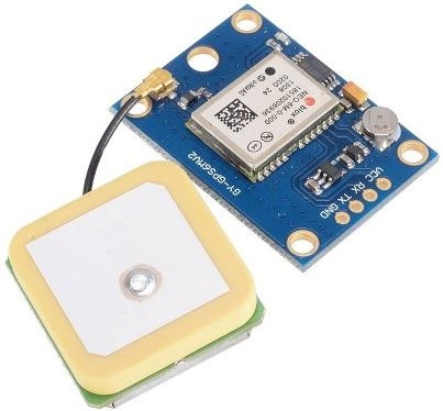
GPS
The NEO-6 series of modules is a family of stand-alone GPS receivers with the high-performance u-blox 6 engine. These flexible and cost-effective receivers offer numerous connectivity options in a miniature package of 16 x 12.2 x 2.4 mm. Its compact architecture and power and memory options make the NEO-6 modules ideal for mobile devices that run on batteries with very strict cost and space constraints. The u-blox 6 50 channel positioning engine features Time-To-First-Fix0 (TTFF) of less than 1 second. The dedicated acquisition engine, with 2 million correlators, is capable of performing massive parallel time / frequency spatial searches, allowing you to find satellites instantly. Innovative design and technology suppress sources of jams and mitigate multipath effects, giving NEO-6 GPS receivers excellent navigation performance even in the most challenging environments.
Specs:
1. Input Voltaje: 2.7 to 3.6V.
2. Current: 67 mA.
3. Antenna Gain: 50 dB.
4. Operating Temeparture: -40 to 85 ° C.
5. Comunication: UART, USB, SPI, DDC.
6. Sensibility.
- Navigation: -160 dBm.
- Cold Start (autónomo): - 146 dBm.
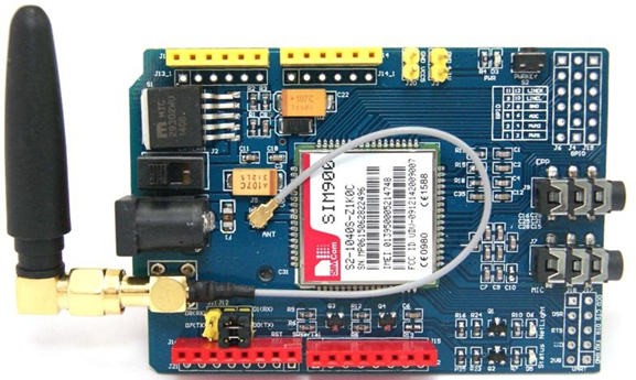
GSM
The GPRS SIMCOM SIM900 GSM Quad Band GSM Shield is an ultra-compact wireless communication card. The GPRS is configured and controlled via UART using AT commands. Ideal for remote systems, recursive communication, control points, sending text messages to cell phones, etc.
Specs:
1. Conecction via Serial.
2. Quad-Band 850/ 900/ 1800/ 1900 MHz.
3. GPRS multi-slot class 10/8.
4. GPRS mobile station class B.
5. GSM phaase 2/2+ Compatible.
6. Class 4 (2 W (AT) 850 / 900 MHz).
7. Class 1 (1 W (AT) 1800 / 1900MHz).
8. Embedded TCP/UP.
9. RTC Support.
GSM
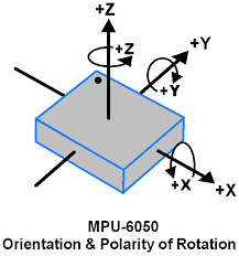
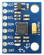
The MPU-6050 is an inertial measurement unit (IMU) of six degrees of freedom (6DOF) manufactured by Invensense, which combines a 3-axis accelerometer and a 3-axis gyroscope.
The communication can be done both by SPI and I2C bus, so it is easy to obtain the measured data. The supply voltage is low voltage between 2.4 to 3.6V. In most modules, this includes a voltage regulator that allows direct powering to 5V.
It has digital analog converters (ADC) of 16 bits. The range of the accelerometer can be adjusted to ± 2g, ± 4g, ± 8g, and ± 16g, the gyroscope range to ± 250, ± 500, ± 1000, and ± 2000 ° / sec.
It is a sensor consumes 3.5mA, with all the sensors and the DMP activated. It has an embedded temperature sensor, a high precision clock and programmable interruptions.
The MPU-6050 incorporates an internal processor (DMP Digital Motion Processor) that executes complex MotionFusion algorithms to combine the measurements of the internal sensors, avoiding having to perform the filters externally.
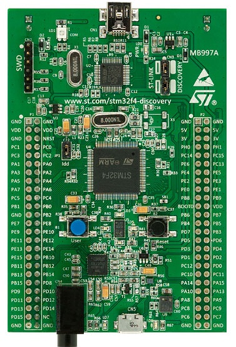
STM32F4 Discovery
The STM32F4DISCOVERY kit takes advantage of the capabilities of STM32F407 high performance microcontrollers. Includes an integrated ST-LINK debugging tool, a ST-MEMS digital accelerometer, a digital microphone, an audio DAC with integrated class D loudspeaker driver, LED, buttons and a USB OTG micro-AB connector.
< br>
SPECIFICATIONS:
1. STM32F407VGT6 microcontroller with ARM® Cortex® -M4 32 bits with FPU core, 1 Mbyte flash memory, 192 Kbytes RAM in a ST-LINK LQFP100 package.
2. USB ST-LINK with counting capability and three different interfaces:
- Debug port.
- Power supply to the board: via the USB bus or an external power supply of 5 V.
- External application power supply: 3 V and 5 V.
3. 3-axis accelerometer LIS302DL or LIS3DSH ST MEMS.
4. MP45DT02 ST-MEMS omnidirectional digital audio microphone sensor.
5. Audio DAC CS43L22 with integrated Class D speaker driver.
6. Eight LED:
- LD1 (red / green) for USB communication.
- LD2 (red) for a power of 3.3 V.
- Four user LEDs, LD3 (orange), LD4 (green), LD5 (red) and LD6 (blue) 2 LED USB OTG LD7 (green) VBUS and LD8 (red) overcurrent.
7. Two push buttons (user and restart).
8. USB OTG FS with micro-AB connector.
9. Extension header for all LQFP100 I / O for quick connection to the prototype board and easy probing.
I2C or Inter-Integrated Circuit is a serial bus of several masters and slaves. This protocol is commonly used with RTC modules, temperature sensors, EEPROM, IO expanders and more.
The I2C protocol uses 2 cables:
- SCL: serial clock, clock for serial synchronization.
- SDA: serial data, bidirectional line to receive and transmit.
Both cables need an external pull-up resistor, from approximately 4k7 to 47k, if you do not use pull-up resistors in the MCU.
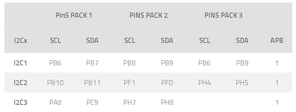
STM32F4 has up to 3 I2C, each of them has a pack of at least 2 pins for each I2C. The pins used for each I2C are described in the table below:
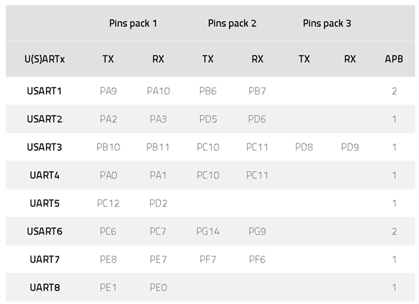
A universal asynchronous receiver-transmitter is a hardware device for asynchronous serial communication in which the data format and transmission speeds are configurable. The levels and methods of electrical signaling are handled by a controller circuit external to the UART. One or more UART peripherals are commonly integrated into microcontroller chips. A related device, the universal synchronous and asynchronous receiver-transmitter (USART) also supports synchronous operation. The pins used for each USART are described in the table below: